
hard metal
Integrated solution

Contact:Mr. Yang
Mobile:+86 17712471756
Mobile:+86 13584960756
Phone:0512-50881555
Email:coolk@syfcarbide.com
Website:www.southvietnamtravel.com
Address:1911 Shuixiu Road, Kunshan City, Jiangsu Province, China
Powder metallurgy series grades
Cracking and wear resistance issues often occur during the pressing of powder products such as copper powder, iron powder, tungsten carbide, ferrite, zirconia, and alumina. We consider the diversity and complexity of product structures and design multiple specialized grades to select materials correctly based on material characteristics for different purposes.
| series | brand | Cobalt content (%) | Density (g/cm3) | hardness | Bending strength (Mpa) | Application scope |
| Powder metallurgy series | CF06F | 6 | 14.90 | 93.3 | ≥3200 | Ultra fine grain, extremely high wear resistance and excellent strength. Suitable for high-pressure molds with simple cavities such as soft magnetic materials, used as negative molds. |
| CF10F | 10 | 14.60 | 92.3 | ≥3800 | Ultra fine grain, high wear resistance. Suitable for high-pressure molds with simple cavities such as soft magnetic materials, used as negative molds and core rods. | |
| CF20 | 7 | 14.75 | 91.0 | ≥3200 | Suitable for powder metallurgy molds such as iron-based and copper based molds, used as negative molds, shaping molds, and core rods. | |
| CF40 | 10 | 14.62 | 89.5 | ≥3200 | Suitable for iron-based, copper based, and hard alloy powder metallurgy molds, used as negative molds and core rods. | |
| VG05 | 12 | 14.32 | 89.0 | ≥3300 | It has high strength and wear resistance, suitable for forming concave dies and punches of iron powder, copper powder, and hard alloys with complex shapes and high pressing pressures. | |
| VG30F | 20 | 13.80 | 88.0 | ≥3400 | Strengthening the liquid phase and using ultrafine grains results in strong fatigue resistance. Suitable for powder metallurgy molds such as iron-based and copper based molds, used for the production of irregular and curved punch heads. | |
| VG15 | 14 | 14.15 | 87.5 | ≥3500 | Good toughness, impact resistance, and good spot processing ability, suitable for high load work and complex mold cavities. |
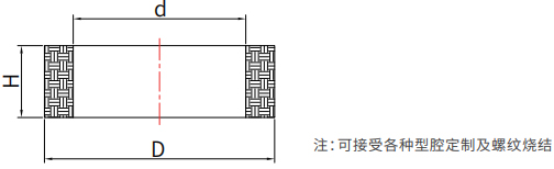
Basic outer diameter dimensions (mm) | Basic height dimensions (mm) | ||||
| ≤30 | 31~64 | 65~109 | 109~159 | 160~240 | |
| Outer diameter (height) tolerance (mm) | |||||
| ≤25 | +1.0 | +1.1 | +1.2 | +1.3 | +1.4 |
| 0 | 0 | 0 | 0 | 0 | |
| 26~39 | +1.4 | +1.5 | +1.6 | +1.7 | +1.8 |
| 0 | 0 | 0 | 0 | 0 | |
| 40~69 | +1.8 | +1.9 | +2.0 | +2.1 | +2.2 |
| 0 | 0 | 0 | 0 | 0 | |
| 70~109 | +2.2 | +2.3 | +2.4 | +2.5 | +2.8 |
| 0 | 0 | 0 | 0 | 0 | |
| 110~159 | +2.8 | +3.0 | +3.2 | +3.2 | +3.5 |
| 0 | 0 | 0 | 0 | 0 | |
| >160 | 2.00% | 2.20% | |||
| 0 | 0 | ||||
| Basic dimensions of inner diameter (mm) | 15 | 16~29 | 30~44 | 45~60 | 60~85 |
| Inner diameter tolerance (mm) | 0-1.0 | 0-1.2 | 0-1.5 | 0-2.0 | 0-3.00% |